Thermador Range E3 and E4 Error Codes Explained
Steven E / Tuesday May 13, 2025
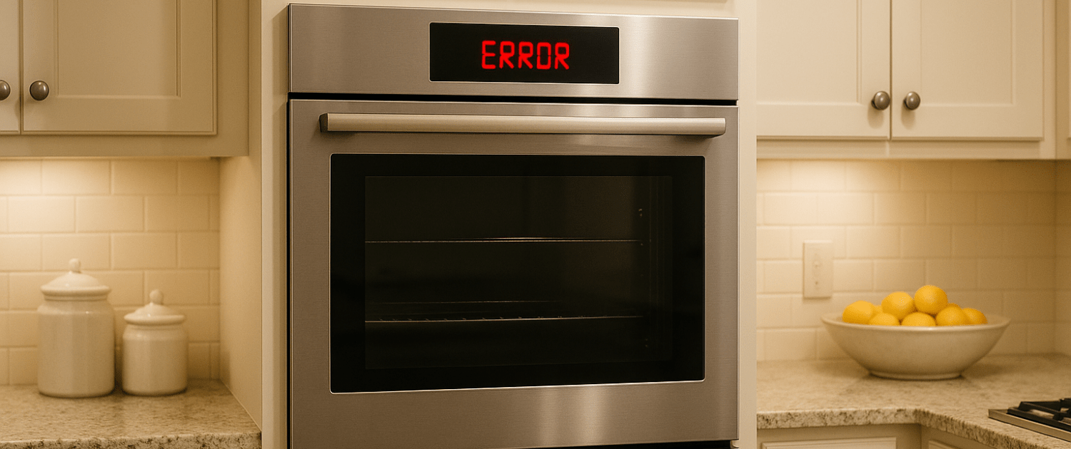
E3 and E4 error codes appearing on Thermador Pro ranges indicate problems with the oven temperature sensor circuit. The E3 error points to an open sensor circuit, while E4 means the sensor is shorted. Resolving these fault codes requires testing sensor connectivity and resistance, checking wiring, and replacing any damaged components. We’ll walk through the full troubleshooting and repair process for E3 and E4 Thermador range sensor errors.
If you find out that you need any replacement parts for your appliance while you’re troubleshooting, you can enter your model number at AppliancePartsPros.com to order them. Most orders arrive in just two business days, and we have thousands of free guides to show you how to install your new parts.
The information in this article may not apply to your specific appliance model. We recommend consulting your manufacturer’s documentation or contact us with any questions.
What causes the error codes?
Inside the oven cavity is a temperature sensor, typically mounted on the rear wall. It monitors heat levels and provides feedback to the electronic control board.
The E3 error code means the control board is seeing an open circuit from the sensor. Possible causes include:
- Faulty sensor wiring connections at the board or sensor
- Loose, damaged, or burnt wires create an open circuit
- Defective temperature sensor requiring replacement
- The failed connection point on the control board
The E4 error signifies a shortened sensor circuit. Potential causes are:
- Bare or damaged wires shorting against the oven chassis
- Moisture or food debris creates intermittent shorts
- Defective temperature sensor with an internal short
- Faulty control board input circuit
So both E3 and E4 indicate a loss of proper temperature monitoring capabilities due to sensor connectivity issues.
Safety precautions
When working on any appliance, remember to keep safety first. Here are some tips to keep in mind:
- Always power off and unplug your appliance or switch off the circuit breaker before attempting any maintenance or replacement work. This keeps you safe by preventing any risk of injury from electric shock.
- Wear insulated work gloves to protect your hands from sharp metal parts, pinching hazards and debris.
- Take your time and don’t rush while working to prevent accidents and personal injuries.
- Work in a well-lit area so you can clearly see and access the interior parts.
- Clear your workspace of clutter and other obstacles. Keep children and pets away from the work area.
- Never work on internal parts with bare wet hands. Make sure the work area is completely dry.
- Check your user manual to see if there are specific installation or safety instructions for your part or appliance.
- Be gentle when handling or removing parts. Excessive force might damage the appliance or cause injury.
- Wear safety glasses when working with chemicals, dust or cleaning large debris to prevent injury.
- If the appliance has recently been used, give it plenty of time for any heating parts to cool down before working on it.
- Take pictures or make a note of wiring terminals or other connections before disconnecting to prevent any problems with reassembly.
- When working with wires, avoid touching any exposed wires or terminals. If you need to touch a wire, use a non-conductive tool or wear insulating gloves to prevent electrical shock.
Troubleshooting steps
Step 1: Inspect wensor wiring and connections
The first troubleshooting steps are:
- Turn off the power to the oven and unplug the unit if possible.
- Remove the bottom oven panel to access the sensor wiring.
- Check that wire connectors at both ends are fully inserted into their terminals. Try unplugging and reinserting connectors.
- Look for any damaged, burnt, or deteriorated wire insulation that could be causing openings or shorts.
- Verify wires are routed cleanly and not pinched behind the oven cavity.
- Inspect the temperature sensor probe itself for cracks or damage which could compromise connections.
- Rectify any wiring issues found. Replace damaged sensor wires or harnesses as needed.
In many cases, the error codes are caused by repairable wiring problems versus defective parts.
Step 2: Test the temperature sensor
If an initial inspection of the wiring and connections reveals no obvious issues, the next step is checking the resistance of the temperature sensor itself using a multimeter.
Measuring the resistance can definitively diagnose if the temperature sensor is functioning properly or is defective and needs replacement.
Here is the complete process for testing sensor resistance:
- Unplug the oven or disconnect the power supply at the main circuit breaker panel. Verify that no power is reaching the appliance during testing.
- Remove the bottom oven access panel to locate and access the temperature sensor wiring.
- Identify the two wires that connect the temperature sensor to the electronic control board. These may be a red and white wire pair.
- Carefully disconnect the two sensor wires from their terminals on the control board. You will attach multimeter probes to these wires.
- Set your multimeter to measure resistance in Ohms (Ω). Digital multimeters work best for accuracy.
- Touch the multimeter probes to the two disconnected sensor wires. It does not matter which probe touches which wire.
- With the probes attached and the meter powered on, check the resistance reading displayed.
- Consult the resistance specification for the sensor in your oven model’s service manual. For example, a typical range is 1,000 Ω at room temperature.
- The observed ohms reading should closely match the expected sensor resistance value for the current ambient temperature.
- To further validate the sensor condition, use a hair dryer to gradually heat the sensor probe while monitoring the resistance value.
- Resistance should steadily increase as the temperature rises without any erratic jumps. Erratic resistance fluctuations that do not consistently follow temperature changes indicate a faulty sensor that should be replaced.
- If resistance is different from the specification, the sensor is likely defective and will need replacement.
Following this reliable resistance testing process provides a clear pass/fail diagnosis of the oven temperature sensor before replacing other components. Consult service manuals for exact specification values.
Step 3: Replace a faulty oven temperature sensor
If multimeter testing confirms the oven sensor is defective, replacement is required:
- Order the replacement temperature sensor specific to your Thermador model by clicking here and using our compatibility tool.
- Turn off the power, remove wires, and extract old sensors from its mount.
- Without damaging the connection tip, install the new oven sensor in the same position.
- Reconnect wires to the control board, taking care to match terminals.
- Restore power, calibrate the new sensor, and test oven functionality.
Be very careful handling the delicate probe tip of the replacement sensor during installation.
Once a faulty oven temperature sensor has been replaced with a new unit, the electronic control board must be recalibrated to properly interpret resistance values from the new sensor.
Step 4: Recalibrate the sensor
Recalibration is needed for accurate cooking temperatures and preventing error codes from reappearing. Here are the steps:
- Locate the recalibration sticker on the back of the oven or inside the oven door. It will display a 5 or 6-digit offset number. This is the target value you will dial in.
- Enter service mode by pressing Bake, Broil, and Clean simultaneously and holding for 3 seconds until the oven display flashes.
- Press the Bake button once to display the current temperature sensor offset value.
- Use the up and down arrows under the Bake and Broil buttons to incrementally adjust the offset number higher or lower.
- Adjust in small increments of 5°F or 3°C until the displayed offset matches the target number printed on the recalibration sticker.
- When the values match, press the Clean button once to exit service mode. Avoid holding Clean for more than 2 seconds to prevent activating self-clean.
- The new sensor is now calibrated and paired with the control board.
To validate, run an oven test cycle and verify temperature reaches the expected set point. If temperatures are off, repeat calibration and check the offset number entered carefully. Document the new offset number applied for future reference.
Step 5: Replace the control board
If sensor resistance and connections test good, the electronic control board may be misinterpreting the sensor circuit:
- Order and install a replacement oven control board designed for your model.
- After installing the new board, be sure to complete sensor calibration as described above.
- Retest oven operation. If E3 or E4 errors persist, additional troubleshooting is needed.
Additional information
Thank you for reading! We hope this guide helped you get your range working again.
If you have any other appliance repair needs or projects, don’t hesitate to explore our other troubleshooting guides and videos.
If you need replacement parts or some extra help with ordering them, grab your model number and head over to AppliancePartsPros.com, where you can chat with a pro, read our DIY blog and more.
Be sure to subscribe to us on YouTube and follow us on Facebook, Twitter and Instagram!
With nearly a decade of experience in providing top-notch customer service regarding appliance parts and repair, Steven enjoys sharing practical advice, troubleshooting tips, and interesting information to help readers stay informed.


